


Debug Relay Board RDP
With the Debug Relay Board RDP you minimize ESD events, accidental short circuits, mating cycles and loose contacts on your precious target system. The Debug Relay Board RDP is aimed at targets that cannot be moved via remote desktop - such as Test benches and system controls - or debugging and remote maintenance at the customer's office or home office.
Description:
Contact your target system via the Debug Relay Board RDP with supply voltages, input and output signals, hardware debuggers and USB devices. You can then stimulate, evaluate and operate your target system using the intuitive PC program.
Target systems in hard-to-reach places are connected once via the Debug Relay Board RDP and then operated elegantly remotely.
You can quickly and easily create endurance tests for the target system with the Debug Relay Board RDP and the open protocol. In this way, short-circuit tests and on-off cycles can be automated and monitored remotely.
Bluetooth, WLAN or Ethernet can be implemented on the Debug Relay Board RDP using FeatherBoards from Adafruit. There is a custom-made pin header available for this.
A pair of pin headers with four mounting holes is available for your customer-specific plug-in boards.
The galvanically isolated input side can be expanded using customer-specific boards with shift registers.
Any number of Debug Relay Boards RDP can be managed via a USB host.
Overview of all Features:
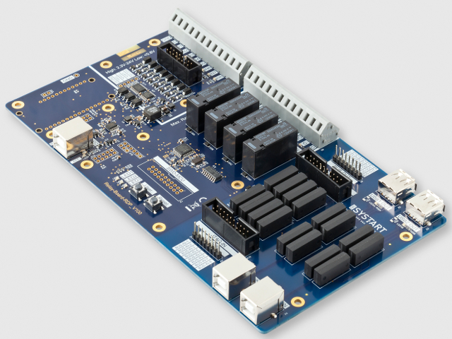
- 4 x Relays up to 2,5 amp and up to 24 VDC (OMRON G6RN-1)
- 8 x Relays switch an 8 bit wide bus e.g. for HW debuggers
- 20-pin JTAG header is also mapped to this bus
- 8 x Digital input - galvanically isolated
- 2 x USB 2.0 switchable - not galvanically isolated
- 15 x LED for visualization of active switching states
- 3 x LED for free use
- 2 x LED to indicate power and USB communication
- 5 Volt Power supply directly via the USB host
- Printed circuit board dimension: 210 x 120 mm mm
- 8 x Mounting holes for attachment to e.g. a board construction
- See also the PDF below with the dimensions
Development documents and files:
- Circuit diagram and assembly diagram
- Configuration file with all commands for the HTerm program
- Protocol definition with examples
Services:
- Adaptation of the hardware to your individual wishes
- Programming endurance tests to meet your requirements
- Extension to Bluetooth, WLAN or LAN
We are happy to discuss all of your requirements and requests, you can contact me by phone at 08142/305050 or by emaill m.bittner@ebs-systart.com.
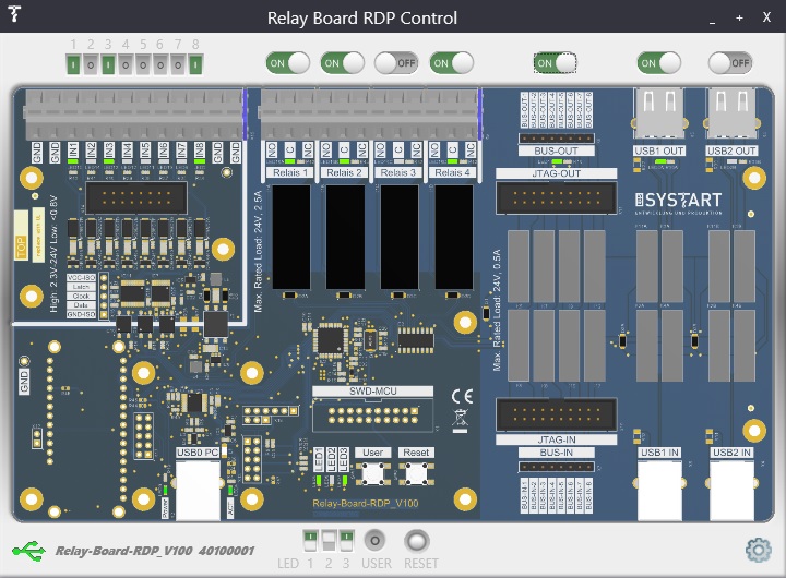
PC Software "Relay Board RDP Control":
You can download the installer package for the Windows PC software using the link below.
![]() Relay_Board_PC-Software_V003.zip
Relay_Board_PC-Software_V003.zip
Instructions implementation Bluetooth and WLAN:
The following PDF shows the implementation of Bluetooth and WLAN. The FEATHER BOARD HUZZAH32 – ESP32 (Product ID: 3405) from Adafruit is used. The zip folders contain the necessary demo programs.
![]() Relay-Board_Bluetooth_and_WIFI_en_V002.pdf
Relay-Board_Bluetooth_and_WIFI_en_V002.pdf
![]() Relay-Board-RDP_BT-Demo_V100.zip
Relay-Board-RDP_BT-Demo_V100.zip
![]() Relay-Board-RDP_WLAN-Demo_V100.zip
Relay-Board-RDP_WLAN-Demo_V100.zip
![]() hterm_commands_V100.zip
hterm_commands_V100.zip
General documents:
![]() Relay-Board_Communication_Protocol_en_V101.pdf
Relay-Board_Communication_Protocol_en_V101.pdf
![]() Schaltplan Relay-Board-RDP_V110_Var1.pdf
Schaltplan Relay-Board-RDP_V110_Var1.pdf
![]() Bestückungsplan_Relais_Board_RDP_V110_Var1.pdf
Bestückungsplan_Relais_Board_RDP_V110_Var1.pdf
![]() Abmessungen Relay-Board-RDP_V100_Var1.pdf
Abmessungen Relay-Board-RDP_V100_Var1.pdf
![]() Step-Datei Relais-Board-RDP_V100.zip
Step-Datei Relais-Board-RDP_V100.zip
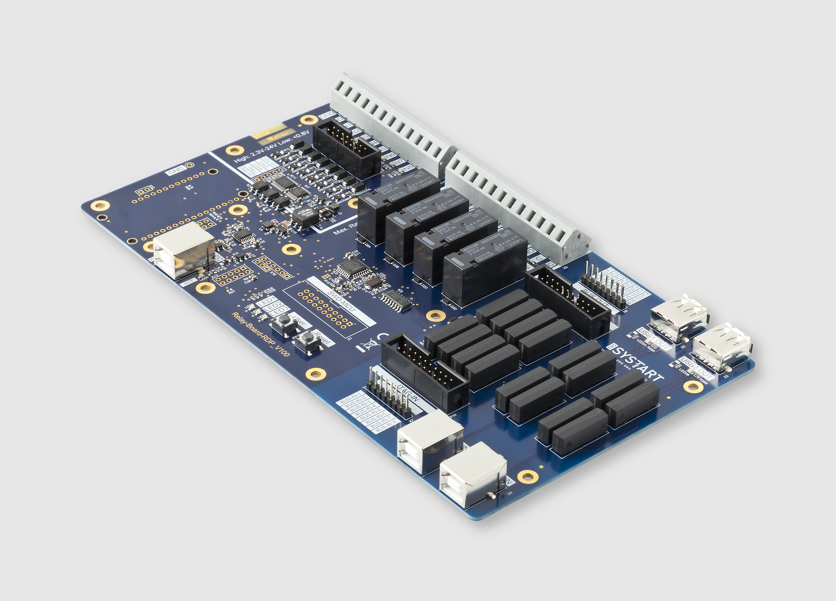 Bild Relais-Board-RDP-Isometrisch.jpg
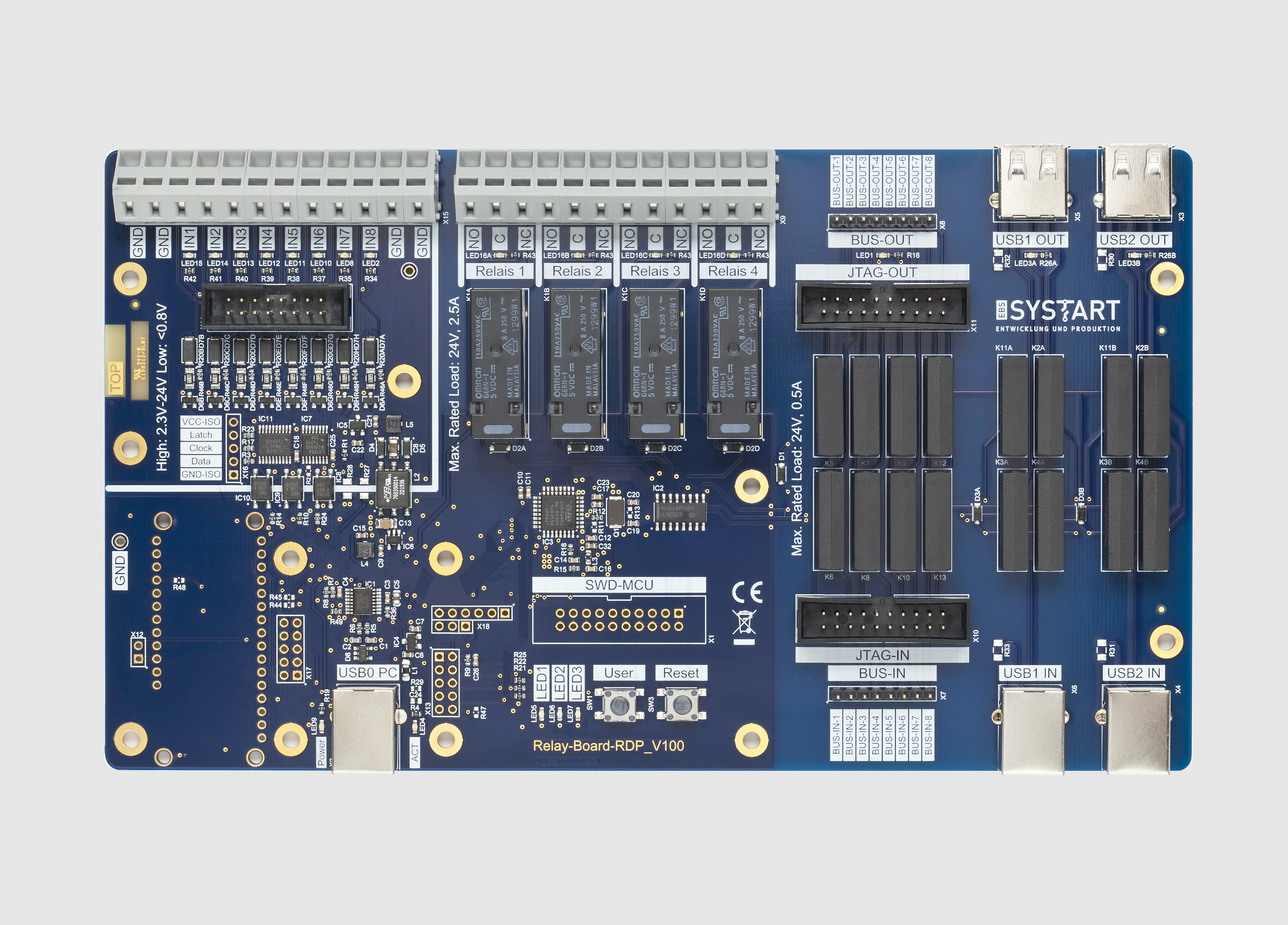 Bild Relais-Board-RDP-Frontal.jpg
Note:
- The Debug Relay Board RDP is only designed and approved for voltage levels and switching voltages of up to 24 VDC.
Contact:
If you have any rquests or adjustments, please contact us at 08142/305050 or via emaill info@ebs-systart.com.